Product Design
The process of creating new products or developing design innovations for enhanced product performance. The design process includes conceptualization, simulation, optimization, and design finalization prior to manufacturing.
Their evolving role has been facilitated by digital tools that now allow designers to do things such as communicate, visualize, analyze, produce 3D models and come up with tangible ideas in a way that would have previously required greater human resources.
Customers
Below is a small selection of companies that use our products.
Aerospace
- Boeing
- Bell
- ONERA
- Lockheed Martin
- GE Aerospace
- German Aerospace Center
- Leonardo
- Rolls-Royce
Automotive
- Porsche
- Hyundai
- Komatsu
- Honda
- Toyota
- NHK Spring
- BMW
- CLAAS
Motorsport
- Scuderia Alpha Tauri
- Ducati Corse
- Richard Childress Racing
Healthcare
- Carestream Dental
- UC Care
- Bruker
Consumer Products
- Black & Decker
- Harman
- Hilti
Electronics
- Intel
- Emcore
- Samsung
- Anca Motion
- Sony
- VectorNav
HVAC
- Daikin
- Hitachi
Power Management
- EATON
Shipbuilding
- Samsung Heavy Industries
- Hyundai Heavy Industries
- North Sails Nevada
Tires
- Pirelli
- Cooper Tire
Drive Train
- Renk
FAQ
Yes, when you load the DWG file in the Drawing workspace, layouts are available under the Drawing.Sheets property.
Want to see our products in action?
Watch the Made with Eyeshot videos playlist
Code Samples
Below is a selection of code samples related to these industrial sectors.
Assemble
This sample provides instructions for assembling individual objects using direct, transformation, and animation methods.
AssemblyDemo
This sample showcases Eyeshot's capability to handle large assemblies. It includes several useful commands such as Form New, Dissolve, Edit Structure, Make Independent, Edit Part, Edit Assembly, Edit Parent, and Moved with Triad. You can control selection, visibility, and selectability at the instance level. AssemblyDemo allows selection in branch or leaf mode and commands to open/save and import/export in IGES/STEP file formats. Asynchronous regeneration, disabled shadows, disabled reflection, disabled silhouette curves, and show center of rotation are the default settings for this sample. Video1, Video2, Video3
Barbecue
This sample demonstrates how to create a 3D model of a barbecue using Brep boolean operations and sheet metal flanges.
BlendSurface
This sample explains how to build a blend surface between two surface edges. You can interactively change the influence of each edge. The Extend button allows you to smoothly extend the surface edges. Video1
CollisionDetection
This sample explains how to properly animate a robot arm and how to check collisions between objects. The additional tab is dedicated to 2D collision detection instead. For more details on the collision detection implementation, check this this article.
Defeature
This sample demonstrates the process of identifying and eliminating topological elements from a BRep object. Video1
Dimensioning
This sample explains how to interactively measure a 3D model. Video1

DraftAnalysis
This sample demonstrates how to split a Mesh entity based on a pull direction and animate BlockReferences using a standard trackbar.
ExplodedView
This example illustrates how to create assembly configurations with varying component positions and visibility states, and how to generate drawings from these configurations.
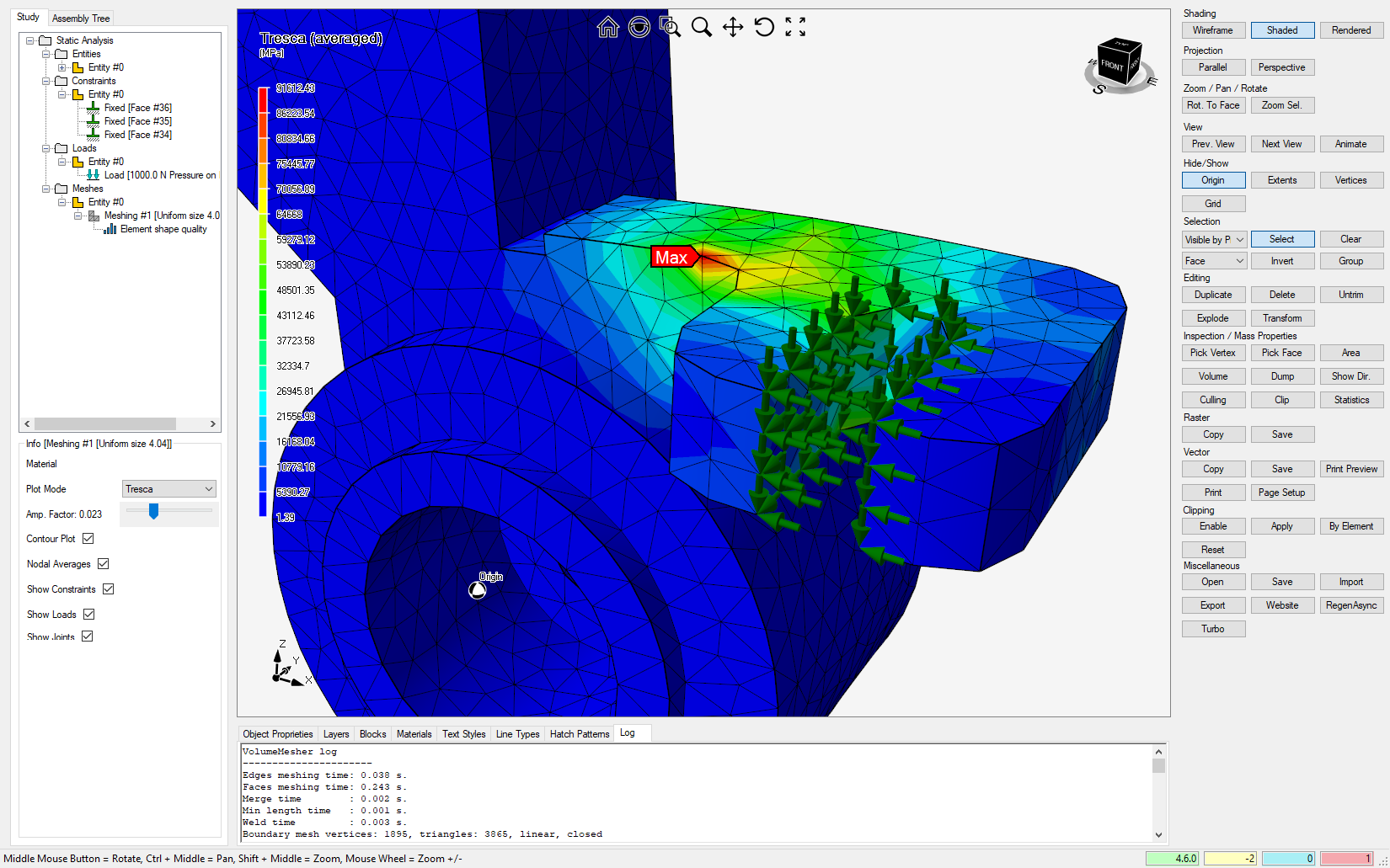
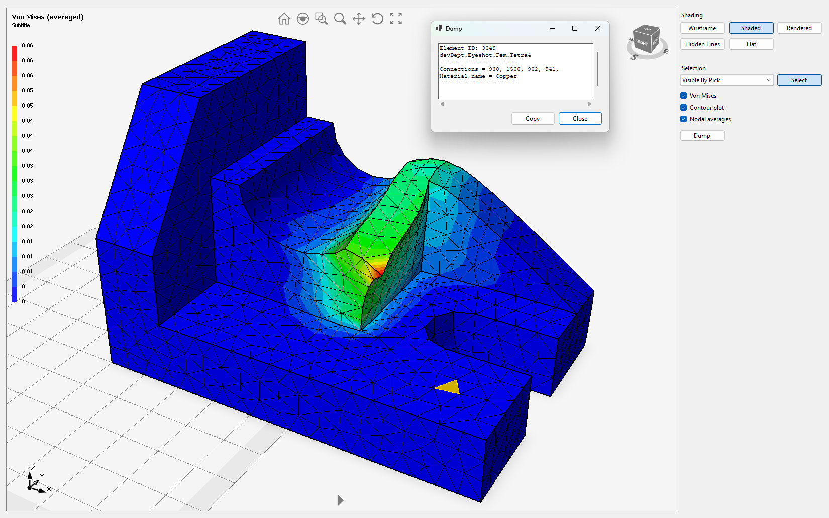
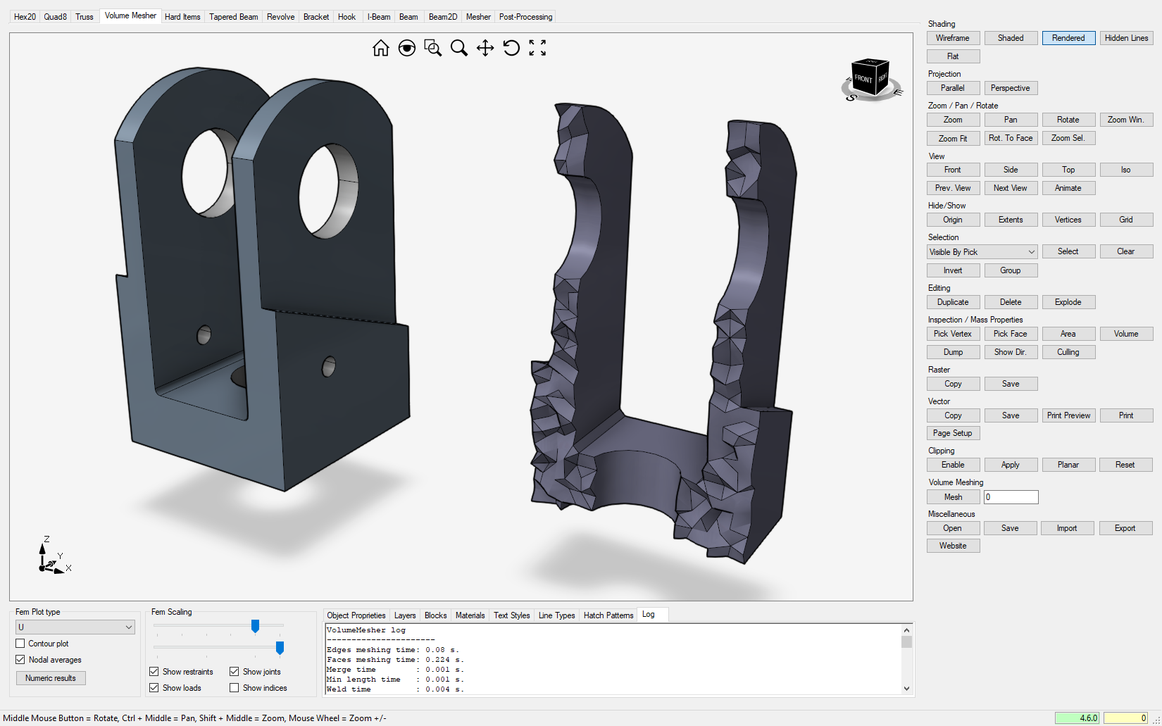
FemDemo
This sample covers the volume meshing of arbitrary geometry, the elements' quality histogram, the application of boundary conditions on BRep vertices/edges/faces, linear static analysis, and the plot of results. Video1, Video2
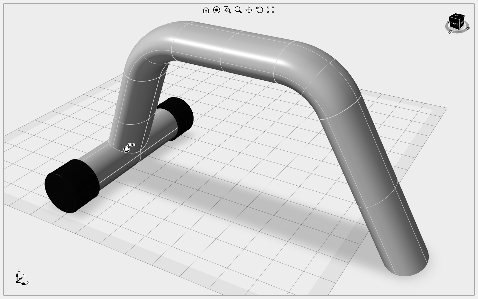
Gym
This sample demonstrates how to create a gym frame using NURBS surfaces.
ImGui
This sample demonstrate how to use the QuickForm tool described here to interactively change the NURBS surface tessellation.
ObjectManipulator
This sample provides instructions on setting a BlockReference as current and interactively modifying its position and orientation using the ObjectManipulator widget.
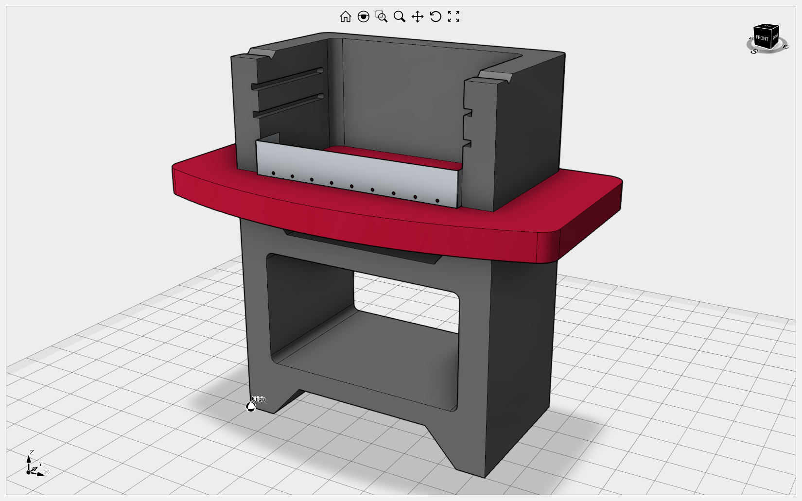
PaperDemo
This detailed demonstration explains how to generate Vector and Raster views of your geometry in the Drawing workspace. It is the only example that allows for the import of DXG/DXF files that include AutoCAD paperspace or layouts. Import of STL, OBJ, IGES and STEP files are provided to test the view generation quality on your own geometry. The Drawings tab contains a variety of options to add dimensions and annotations to the views. Drawing sheets can be exported to DWG/DXF as VPORT objects or exploded curves. Yes, you are right, the geometry belongs to our office desks as you can check here. Additionally, this demonstration shows how to use the WorkManager class to handle a queue of WorkUnits for building the views. Ready to start? Check this introductory article for more information. Video1, Video2
Routing
This sample explains how to draw and shape an electrical wire or flexible pipe. You can add multiple joints and move them using the right mouse button.
SelectElements
This sample explains how to implement individual FEM elements selection for a FemMesh entity.
Simulation
This sample illustrates Eyeshot's Finite Element Analysis capabilities, including mapped meshing and 2D and 3D beams with hinge support. Clicking the "Numeric results" button opens a dialog displaying all the results in a tabular view. Video1
SketcherDemo
This sample shows how to utilize the 2D constraint solver from UI, including sketch extrude/revolve/sweep and assembly navigation to a specific component/BRep. The left pane contains the assembly and features trees, and it also offers the option to import a sketch from DWG/DXF. Video1, Video2, Video3
SlicerDemo
This sample provides instructions for slicing a 3D mesh for printing and simulating the extrusion process. Video1
SurfaceMesher
This sample explains how to control the size of elements in surface meshing and provides tools for evaluating the quality of triangle shapes. Video1
SurfaceSection
This sample explains how to generate a section of a 3D surface model.
Wing
This sample demonstrates the process of creating a manifold BRep object from two airfoils, which can then be exported in STEP file format.
Workspaces
This sample showcases how Eyeshot workspaces (previously known as Environments) seamlessly operate on the same geometry. It also demonstrates the process of defining 2D sketches, orthographic views, FEA study, and 3x CNC machining programmatically. Video1